Product Categories
- Marine Cable
- Marine Power Cable
- Marine Communication Cable
- Marine Control Cable
- Offshore Cable
- Crane Cable
- Mining Cable
- Electrical Cable
- Solar Cable
- Underwater Cable
- Wind Cable

Type SHD Power Flat Portable Cable 2KV
Type SHD Power Flat Portable Cable 2KV Application
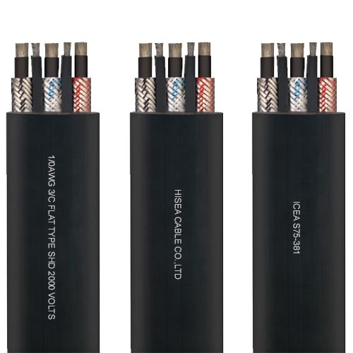
These flat parallel cables are designed for use on continuous miners requiring grounding conductors and metallic shielding over each conductor.
Designed for use as trailing cables on AC mining equipment:
-Where induced voltages in the grounding system will not produce a hazard
-On low- and medium-voltage AC circuits where shielding is desired or required
Type SHD Power Flat Portable Cable 2KV Applied Standards
ICEA S-75-381/NEMA WC 58
ASTM B 172
ASTM B 33
Type SHD Power Flat Portable Cable 2KV Constructions
Conductor:
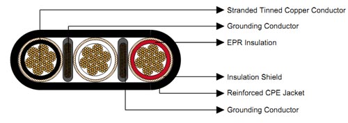
2 AWG thru 3/0 AWG coated annealed copper, bunched wires, rope-lay-stranded per ASTM B172
Insulation:
Ethylene Propylene Rubber (EPR) insulation
Insulation Shield:
A flexible coated copper/textile braid shield is applied over a non-conducting overlapped tape
Grounding Conductors:
Coated copper, rope-lay-stranded per ASTM B172 Two conductors, shaped and covered with an extruded semi-conducting shield

Jacket:
Reinforced, extra-heavy-duty, lead-cured Chlorinated Polyethylene (CPE)
Options
Other jacket materials such as CSP/PCP/NBR/PVC are available upon request
Two-layer jacket with reinforcing fibre between the two layers can be offered as an option
Mechanical and Thermal Properties
Minimum Bending Radius: 6×OD
Maximum Conductor Operating Temperature: +90℃
Type SHD Power Flat Portable Cable 2KV Features:
Flexible insulation shield provides shock hazard protection
Excellent heat, moisture, steam, oil, chemical and radiation resistance
Flexible for easy handling
Resists cutting, impact, abrasion, flame and sunlight
Excellent thermal stability and physical properties over a broad temperature range
Type SHD Power Flat Portable Cable 2KV Specifications
|
Construction |
No. of Strands |
Grounding Conductor Size |
Nominal Insulation Thickness |
Nominal Insulation Thickness |
Nominal Overall Diameter Height×Width |
Nominal Weight |
Ampacity |
||||
|
No. of cores×AWG/kcmil |
– |
AWG/kcmil |
inch |
mm |
inch |
mm |
inch |
mm |
lbs/kft |
kg/km |
A |
|
3×2 |
259 |
6 |
0.07 |
1.8 |
0.125 | 3.2 |
0.94×2.45 |
23.9×62.2 |
2243 |
3338 |
159 |
|
3×1 |
259 |
5 |
0.08 |
2.0 |
0.140 | 3.6 |
1.04×2.64 |
26.4×67.1 |
2540 |
3780 |
184 |
|
3×1/0 |
259 |
4 |
0.08 |
2.0 |
0.140 | 3.6 |
1.08×2.82 |
27.4×71.6 |
2915 |
4338 |
211 |
|
3×2/0 |
329 |
3 |
0.08 |
2.0 |
0.155 | 3.9 |
1.18×2.99 |
30.0×76.0 |
3346 |
4980 |
243 |
|
3×3/0 |
413 |
2 |
0.08 |
2.0 |
0.155 | 3.9 |
1.25×3.29 |
31.8×83.6 |
3890 |
5789 |
279 |
Ampacity-Based on a conductor temperature of 90℃ and an ambient air temperature of 40℃, per ICEA S-75-381.